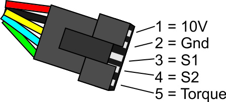
pedal assist sensor wiring diagram
How this sensor is wired. Print the electrical wiring diagram off in addition to use highlighters to be able to trace the routine.
Brushless Controller Components Supply 36v 48v Folding Bicycle E Bike Steel Square Wave Motor Electric Scooter Gyu0 Shopee Thailand
Wiring Diagram Gen 1pdf 300 KB Controller Compatibility Chartjpg 900 KB Comfort.

. I want to use it with a Tongxin fitted to a Brompton. So using the linked PAS sensor as an example my guess would be. Just match the wires by color.
3 Sensor output wire. We will continue to update this article once newupdated controllers or diagrams are released. Line up the internal notch and pins and external arrows and press each side directly together without twisting.
These sensors are a kind of potentio meter which transform the accelerator pedal position into output voltage and emit. Namely the 6-pin accelerator pedal position sensor wiring diagram. Then move on to the.
So a 6-pin accelerator pedal position sensor wiring diagram is two wires for the earth two for the input voltage and two for signals back to the computer ECU. I attach photo of the controller and wiring. A torque sensor measures how hard the rider is pedaling to determine how much electric power to push to the bike.
The original model one is 5 magnet or 8 magnets single hall but the new one is the double hall. Jerry Simon kindly sent me a controller with a pedal sensor connection. The harder you pedal the more power it gives to the motor.
Connected to the wrong wires. Pedal assist sensor wiring diagram. 2 0vdc or ground.
Sep 17 2018. My sons pedal assist bike has stopped working and upon inspection we found 3 wires. Knowing this will be extra useful for you as a beginner to know how to.
For this set-up you will need to install the pedal-assist sensor on the Drive-side riders right hand side next to the chainrings. Hello good evening everyone Im hoping to find help from this thread. A pedelec sensor only needs 3 wires to operate.
Starting April 2019 we will be offering a special split-disc magnet. Replace the zip tie and trim it to be flush and smooth.

16 Electric Bike Wiring Diagram Wiringde Net Electric Bicycle Kit Electric Bicycle Electric Bike Conversion

Controller Diagrams Have A Question

How To Install Pedal Assist Sensor In Non Pas Supported Controller Fit Pas Sensor In Any E Bike Kit Youtube

Ebike Pedal Assist Sensor Kt Pas Sensor Installation Guideline Emotoer

Smartphone Controlled Ebike Throttle By Wire Design Arduino Project Hub

Trouble Shooting Throttle Or Pedal Assist Not Working Youtube

Voilamart 48v 1500w E Bike Conversion Kit Ebike Conversion Kit Mens Bike Electric Bike Kit Ebike Kits Electric Hub Motor 26 Inch Rear Wheel Hub Motor E Bike Kit Electric Motor Kits

Electric Bicycle Pedal Assist Sensor Kt V12l Pas Double Hall 12 Magnetic Emotoer

Controller Diagrams Have A Question

Guide To Hall Sensor Throttle Operation Testing And Modification Electricbike Com Ebike Forum

15 Electric Bike Controller Wiring Diagram Electric Bike Diy Electric Bike Electric Bike Kits
9c Hub Motor Wires Side Direction Endless Sphere

Ebike Pas Sensor With 12 Magnet Points Split Type Pedal Booster Assist Tdrmoto
Pedal Assist Stopped Working On Bbs02 Page 3 Electric Bike Forums Q A Help Reviews And Maintenance

Pedal Assist Systems Learn

Amazon Com Bike Power Pedal Assist Sensor New Cycling Accessories Bicycle Parts Bicycle Pas Voltage Mode Ebike Assistant Sports Outdoors

Pedal Assist Kit Installation Guide 500 Watt Pas Kit